Part 1: What is a balun, what does a balun do, and when is a balun needed?
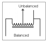
What is a balun?
A balun (mashup of balanced and unbalanced) is a three-port device, or a type of broadband RF transmission line transformer, with a matched input and differential output that is used to connect balanced transmission line circuits to unbalanced ones. A balun’s function is to make systems of different impedance or differential/single-ended compatible and are found in modern communication systems, including cell phone and data transmission networks.
What does a balun do?
Baluns have three basic functions:
1. Unbalanced to balanced conversion of current or voltage
2. Rejection of common mode currents with some configurations
3. Impedance transformation with some configurations (impedance ratios other than 1:1).
There are many types of baluns and include devices that transform impedances and to connect lines of differing impedance. Transformer baluns help with impedance matching, DC isolation, and in matching balanced ports to a single ended port. Common-mode chokes are also used as baluns and work by eliminating common mode signals. Baluns are used in push-pull amplifiers, wide-band antennas, balanced mixers, balanced frequency multipliers and modulators, phase shifters or whenever a circuit design requires signals on two lines that are equal in magnitude and 180 degrees out of phase.
When do you need a balun?
Baluns are most often used to interface an unbalanced signal to a balanced transmission line for long distance communications. On balanced transmission lines, differential signaling is more immune to noise and crosstalk, can use lower voltages, and is more cost effective than single-ended signaling on coaxial cables. Thus, baluns are used to interface local video, audio, and digital signals to long distance transmission lines. Baluns are present in:
– Radio and baseband video
– Radars, transmitters, satellites
– Telephone networks, wireless network modem/routers.
Balun Operation
Ideal S-parameters of a balun:
S12 = – S13 = S21 = – S31
S11 = -∞
The two outputs will be equal and opposite
– In frequency domain this means the outputs have a 180° phase shift.
– In time domain this means the voltage of one balanced output is the
– negative of the other balanced output.
One of the two conductors is clearly grounded.
For example, conductors having equal and opposite potential constitute a balanced line. Microstrip and coaxial cables use conductors of different dimensions and these are said to be unbalanced. Baluns are designed to solve problems caused by this imbalance in that a balun will transition between a balanced or differential transmission line where opposite currents both travel in transmission lines and an unbalanced, or single ended transmission line, where the return current travels through the ground.
In a coaxial cable, the currents on the inner conductor and the inside of the shield are equal and opposite because the fields from the two currents are confined to space in between. Skin effect allows a different current to flow on the outside of the shield which, if significant, causes the feedline to act like an antenna, radiating a field that is proportional to this current. Since it is physically symmetrical and the currents flowing through the conductors are equal and opposite, the radiation from the line is minimal. However, several factors may cause the currents in the two conductors to be imbalanced, that is, other than equal and opposite and, if this is the case, the balanced feed line will radiate like a coaxial cable that has current on the outside of the shield. This imbalance can cause pattern distortion, interference, and loss.
Key specifications in determining the type of balun for a specific application include:
- Frequency coverage
- Phase Balance
- Amplitude Balance
- Common Mode Rejection Ratio
- Impedance Ratio/Turns Ratio
- Insertion and Return Loss
- Balanced Port Isolation
- DC/Ground Isolation
- Group Delay Flatness