Network parameters are mathematical tools used to describe the behavior of linear and non-linear networks, specifically electrical networks based on steady state stimulus. These parameters are heavily used with RF/microwave engineering and electronics that work with high frequency signals. At higher frequencies network parameters, such as S-parameters are often viewed as more useful methods of gauging and comparing a network’s performance than using currents and voltages.
ABCD, S, Y, Z, h, and T parameters are all part of a family of linear network parameters that share many traits and can be readily converted amongst each other with relatively simple mathematical operations. How the various network parameters are generated, however, differs greatly. For instance, S-parameters, or scattering parameters, are generated by applying matched loads to each port and measuring the inputs and outputs from each port. This is done when Network Analyzers generate and receive signals to and from a DUT to its respective ports. Other parameters use shorts, opens, and load terminations.
The result of using network parameters is that the gain, insertion loss, return loss, VSWR, reflection coefficients, and other aspects can be systematically captured and analyzed with common tools used throughout the RF/microwave industries. Simulators that work with network parameters often use ABCD parameters for calculations and present the information to users in the form of S-parameters. Certain applications traditionally prefer specific network parameters over others, which is often a result of the type of components, devices, and testing that is done with that application.
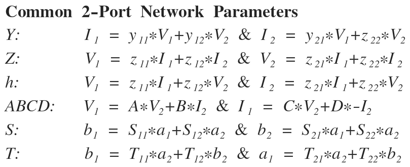
The following are equations for converting network parameters for two-port networks:
A compact two-port network diagram with indicators for voltage, current, and AB parameters
X-parameters are a generalized version of S-parameters that account for nonlinear behavior. These parameters are used to characterize relative phase harmonics and amplitudes for components and devices that exhibit nonlinear behavior when subject to high input power stimuli. X-parameters are generated by nonlinear vector network analyzers, or large signal network analyzers, and extend the S-parameters to account for large signal behavior, as nonlinear impedance, nonlinear reflections, and harmonic mixing are not contained within the traditional S-parameter structure. Hence, for small signal purposes, X-parameters can be reduced to S-parameters.
Useful Vector Network Analyzer Links
• Pasternack VNA Calibration Kits
• Pasternack Phase Stable (VNA) Coaxial Cables
• Pasternack Cable Generic Test Cable Assemblies
• Pasternack Skew Matched Pair Coaxial Cable
• Pasternack Precision Coaxial Adapters
• Pasternack In-series and Between-series Adapters
• Pasternack RF Coaxial Probe