
RF Electromechanical Relay Switches, RF electromechanical switches, or RF electromechanical relays are a type of RF switch with mechanical contacts driven by electrically driven actuators. The transmission paths within an Electromechanical relay switch are purely passive, and thus exhibit relatively low loss and high isolation compared to active switch technologies. Due to the low loss and low VSWR of this switch type, electromechanical relay switches are often used in test and measurement applications, or other applications where high power and fidelity are required.
Key Takeaways
- • CW (continuous wave) power capacity in electromechanical RF switches decreases as operating frequency increases, because higher frequency brings higher dielectric and conductor losses.
- • The connector and mechanical geometry of the switch often become the limiting factor, not just the internal switching mechanism, e.g., at higher frequencies connector size constrains power handling.
- • Lower-frequency switches (larger connector, more generous geometry) can handle higher CW power, whereas high-frequency (mmWave) switches trade off power for frequency capability.
- • In high-power, high-frequency systems, thermal management, insertion loss, VSWR, and mismatch become critical to maintain safe operating margins.
- • When specifying electromechanical RF switches, it’s essential to check the power vs frequency curve (rather than just a flat power rating) because performance degrades with frequency.
The purpose of this switch type is to route RF signals, even to very high frequencies, to different paths and moderate switching speeds. There are a variety of different types of electromechanical relay switches, with a wide range of coaxial connectors, impedances, and complexity. The simplest of which is a single-pole-single-throw (SPST), but may have several poles and throws, such as a double-pole-double-throw (DPDT) or single-pole-twelve-throw (SP12T). Common coaxial connectors for these types of switches are SMA, BNC, and N, though there are many other connector types available.
Given the mechanical nature of the electromechanical relay switch contacts and electrical actuators, the performance of these switches is affected by a variety of factors. One of the main considerations is the continuous wave (CW) power handling capability of the switch as a function of frequency. It is important to note that the upper frequency limit of coaxial connectorized modules, including electromechanical relay switches, may be limited by the coaxial connector and not merely the internal transmission paths or other electronics or structures. Hence, for many electromechanical relay switches, the internal interconnect and contactor design is made so that the coaxial connector is the limiting factor.
Recommendations for Engineers & Designers
- • If you’re working in the 1–10 GHz range and need tens to hundreds of watts of CW power, select a switch with larger connector interfaces and good thermal paths
- • For mmWave (>30 GHz) applications, expect CW power ratings to fall considerably, so design link budgets accordingly, possibly by reducing power or using high-gain antennas to compensate
- • For test and measurement benches where isolation, low loss, and repeatability matter more than switching speed, electromechanical relays still offer excellent performance but check frequency/power tradeoffs
- • For systems requiring fast switching or large channel counts, consider hybrid designs (relay + solid-state) or PIN-diode switches, and only use electromechanical where the highest fidelity or the highest isolation is required
- • Maintain a working log or table of switch modules showing frequency range, CW power rating, connector type, and thermal/mounting considerations—this helps comparison across suppliers and application use cases.
Moreover, the coaxial connector type also has a maximum power handling capability based on the connector geometry and material construction. Typically, higher frequency capable coaxial connectors have lower power handling, as the frequency capability of a coaxial connector is dictated by the geometry and dielectric properties of the inner dielectric material. As RF losses are greater at higher frequencies, RF relays exhibit lower power handling at higher frequency regimes. This is often provided in the specification as a plot of power handling versus frequency (See Figure 1).
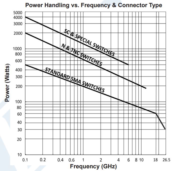
It can be observed from the plot of a DP3T Electromechanical Relay Latching Switch that the higher frequency capable switches (based on coaxial connector type) have lower power handling specifications. Also, at higher frequencies every electromechanical relay switch has lower power handling capability than at lower frequencies.