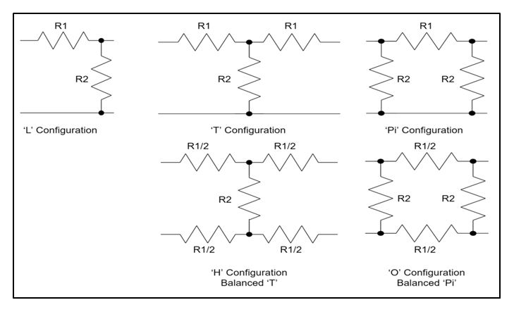
RF attenuators are used to reduce the level of a signal. Some reasons why you might want to reduce the signal level would be to protect a circuit stage from receiving a signal that is too high or in applications where a signal level needs to be controlled.
Attenuators typically consist of a resistive network that allows heat to dissipate at a certain rate. There are a few basic layouts for attenuators—the “T” configuration, the “L” configuration and the “pi” configuration. These established layouts already have set equations and resistor values that can be used to yield the characteristic impedance (Z0) across a range of frequencies, and are also known as unbalanced attenuators with asymmetrical circuits.
The balanced or symmetrical circuit, version of the “T” attenuator, is known as the “H” configuration, and the balanced version of the Pi attenuator, is known as the “O” configuration.

Fixed attenuators are set at a fixed and unchanging attenuation by these resistive networks. These attenuators are placed in signal paths to decrease the power transmitted. Fixed attenuators can be surface mount, waveguide, or coaxial types—depending on the application, also an attenuator can be directional or bidirectional.
A signal can only go from input to output in a directional attenuator and can travel both ways in a bidirectional attenuator.
For a chip-based attenuator, a resistance is developed through various materials deposited onto a thermally conductive substrate, and depending on the process—thick film or thin film—the physical dimensions and the material used will all yield a particular resistance value.
A continuous variable attenuator resistance can also be achieved by arranging an assembly of resistive rods and resistive discs; still, many are built using chips.


 Pasternack Blog
