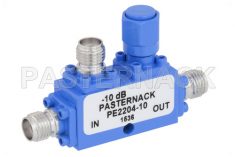
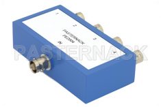
Directional couplers are four port passive devices that employ an input port, output port, a port for the coupled signal and a port that is terminated internally. Directional couplers are used to couple a specific proportion of the power traveling in one transmission line out through another connection or port. Directional couplers are used in many different RF applications ranging from signal sampling to signal generation and signal injection.
Directional coupler design and fabrication poses many of the same concerns and constraints as adapter design and fabrication. Moreover, directional couplers also have the added complexity of requiring built in terminations or forward/reverse coupled signal paths. As the coupled signal paths typically carry hundreds, thousands, or tens of thousands of times less RF signal power than the main propagation line, the lower power levels allow for the use of lower power rated transmission lines.
Even for high powered waveguide directional couplers, low powered coaxial transmission lines may be used as the coupled ports instead of waveguide coupler to reduce the size, routing complexity, and cost of a system. This is obviously not the case for hybrid couplers, or 3dB 90° hybrid couplers, which evenly split the power of a signal in two equal RF signal paths. Hence, these types of couplers require matched signal paths that can handle equivalent power levels.
 Generally, a directional coupler is designed to have very low insertion loss and reflection. At high power levels, the method of coupling can introduce significant insertion loss and reflection, if it’s not precision designed. Another factor to consider is the loading of the coupled lines though at low power levels a simple termination may be adequate. But, at higher power levels any mismatch or reflections could lead to significant power fed back into the main signal path. Furthermore, the terminations of a directional coupler may need to have higher power handling capabilities than their low power counterparts, depending upon the coupling strength.
Much like directional couplers, power dividers split the RF signal energy along multiple paths. Where, power combiners feed the RF signal energy into one main path. The concerns for insertion loss and reflections are much the same with power dividers/combiners as they are with directional couplers.
The major difference is that power dividers/combiners are often at roughly equal power levels, though not phases. As a product of this, any impedance or VSWR mismatch in the connections or feed lines may induce undesired signal degradation, phase deviation, and reflections. Some power dividers/combiners have the inputs or outputs as waveguide or coaxial connections and the inputs and outputs use a different connector size or technology. The frequency and power handling capability for each connection must be accounted for in a final design to ensure acceptable response.


 Pasternack Blog
