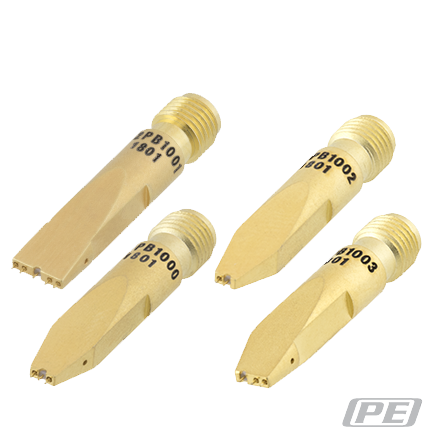
 What is an RF Coaxial Probe?
In RF applications, transmission lines generally are coaxial cables linked to circuit boards and microstrips within circuit boards. An RF coaxial probe is a measurement device used with electronic test equipment in the measurement of radio frequency (RF) signals in an electronic circuit as found in silicon wafers, dies, and open microchips. RF coaxial probes are also used with narrow pitch or high density RF interconnect applications in connector assemblies.
Prior to the development of RF probes in the 1980’s, there was no convenient way to test Monolithic Microwave Integrated Circuit (MMIC) devices without mounting or bonding, which often damaged the integrity of the circuit, contributed to interference in the system, or reduced the power load. First generation RF probes used coplanar ceramic feeds and covered up to 18 GHz. Development in RF probes have led to RF coaxial probes having spring-loaded inner and outer conductors that are used in modern communication electronics. Today, RF coaxial probes continue to be useful in the testing of RF switches, RF traces in printed circuit boards, terminations, and other RF components. Consumer products in the 60-80 GHz mmwave band include use in automotive radar systems. WiGig standards testing and compliance, wireless HDMI, and high performance-LAN.
Why Do We Need Probes?
RF circuit measurement is tricky due to the sensitive and often delicate nature and composition of the devices under testing or DUT. Concerns in reliable RF measurement often occurs when the frequency is too high for available test equipment to measure the RF energy or when a circuit sensitive to small changes in the electrical environment needs to be measured without disrupting the frequency or amplitude. The solution is a measurement probe that disrupts the energy from the circuit as little as possible where high impedance probes are used which may include an amplifier to level the amount of energy harnessed from the circuit, For RF circuit systems testing, matching probe impedance with the testing device is crucial for efficient power transfer, which becomes increasingly challenging as frequency increases and tolerances become more strict. In RF testing, various types of RF test probes are available with suitability based on consideration of the test point to be contacted, the frequency or data rate, the space available for probe installation, and environmental conditions. In the near future, RF probes will need to have the design capability to probe smaller pads with the ability to probe multiple channels and possess the measure range capacity to include multiple mm-wave, RF, logic, and power channels simultaneously.
Important Probe Parameters
When considering high-frequency testing, high-frequency product components require sophisticated test equipment which may include a vector network analyzer (VNA), wafer probe system, high-frequency probes, semi-rigid or flexible coaxial RF cables, and calibration substrates. Perhaps the most critical part of the measurement system is the probe which must physically connect with the DUT. A reliable RF probe should demonstrate impedance repeatability with no degradation from its characteristic (50 Ohms commonly) impedance with no visible or physical wear on mating connectors after repeated insertions.
Frequency Matching
Based on the application of the circuit, a probe that operates up to the operation frequency is recommended; some probes are designed to support frequencies up to 110 GHz. Most RF probes are 50 ohm impedance although high-impedance probes, differential probes, and dual-signal probes (SGS) are available for high-frequency testing purposes.
Configuration
In order to probe a circuit, a signal is sent through a transmission line to the DUT. RF probes require at least two conductors, a signal and a ground, and how these conductors are configured determines the type of probe required for testing the circuit. Configurations include GS (Ground and Signal), GSG (Ground, Signal, Ground), and GSSG (Ground, Signal, Signal, Ground). The most common type of RF probe configuration is the GSG which is similar to coplanar waveguide.
Probe Pitch
Probe pitch is the distance between the tips of the probe and its center. Typical values are 150/250 microns, but a range of 50 to 1000 microns is possible however, larger probe pitch is not practical for millimeter-wave frequencies.
Touch-down
A touchdown is the motion of the probe tip as it comes in contact with the surface of a wafer, component, or printed-circuit board in which the probe exerts enough force to measure the DUT, but not enough force to damage the DUT’s surface.
Probe stations
Probe stations are designed to allow the positioning of RF probes on a silicon wafer so that testing from basic continuity or isolation checks to full functional testing of microcircuits can be run either before or after the wafer has been adapted to individual dies.
Probe skate
When the Z-axis of a probe adjusts as it comes in contact with the DUT and travels along the Z-Y plane as it flexes. A desirable skate probe is one mil or 25 um. The more overtravel (OT) or downward pressure is applied to the probe, the more the probe will skate across the pad. To tolerate excessive OT, a lower skate ratio is required.