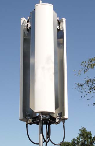
 An antenna array, or phased array, is a set of two or more antennas whose signals are combined in order to improve performance over that of a single antenna. An antenna array is used to increase overall gain, provide diversity reception, cancel out interference, maneuver the array in a particular direction, gage the direction of arrival of incoming signals, and to maximize the Signal to Interference plus Noise Ratio (SINR). An array antenna is usually made up of more than one dipole but it may be composed of driven elements. As these antennas elements radiate individually and while in array, the radiation of all the elements sum up, to form the radiation beam, which has high gain, high directivity and better performance, with minimum losses. Similar to the dipole, a driven element can function as a transmitter or a receiver. When connected to the transmission line, a driven element gets power directly from the transmitter or, as a receiver, transfers the received energy directly to the receiver. Applications of array antennas include satellite communications, wireless communications, radar communications, and in the astronomical study.
Types of Arrays
Arrays can be described by their radiation patterns and the types of elements in the system. When placed close enough to the driven element to permit coupling, a parasitic element will produce the maximum transmission radiation from its associated driver. When a parasitic element reinforces power from the driver, it is referred to as a director. When a parasitic element causes maximum energy to radiate towards the driven element, the element is called a reflector. An array antenna is known as a driven or connected when all of the elements in an array are driven. Interestingly, if one or more elements in the array are parasitic, the entire system is said to be a parasitic array. Multi-element arrays are usually associated with their directivity, for example, a bidirectional array radiating in opposite directions or a unidirectional array radiating in one direction.
Driven arrays
Collinear array
Unidirectional, high-gain antennas designed with two or more half-wave dipoles placed end to end and seated on a common line or axis making them parallel or collinear. The main purpose of this array is to increase the power radiated and to provide high directional beam by avoiding power loss in other directions. Advantages of collinear array antennas include increasing directivity with a reduction in power losses.
Broadside array
Bidirectional array used to radiate electromagnetic waves in specific direction to enhance transmission. The design elements include two or more half-wave dipoles of equal size and equally spaced along a straight line or axis forming collinear points with all dipoles in the same phase from the same source. The broadside array antenna has a radiation pattern that is perpendicular to the axis with a narrow beam radiation pattern and high gain.
End-fire array
Similar to the broadside array and uses two half-wave dipoles spaced one-half wavelength apart with a bidirectional radiation pattern with narrower beam widths, lower gain, and higher directivity than the broadside array. The direction of radiation is along the plane of the array and perpendicular to the elements which radiates to the end of the array, hence the name.
Parasitic arrays
Yagi-Uda array
The most common type of antenna for home TV reception with high gain and directivity. In this antenna, several directors are positioned to increase the directivity of the antenna. The disadvantages of Yagi-Uda antennas are that they can be prone to noise and atmospheric effects.
Log-periodic array
An array antenna whose impedance is a logarithmically periodic function of frequency. Similar to a Yagi-Uda, the advantage of this antenna is that it maintains constant characteristics over a desired frequency range of operation with the same radiation resistance, SWR, and gain and front-to-back ratio are also the same. Types of log-periodic antennas include the planar, trapezoidal, zig-zag, V-type, slot and the dipole or LPDA (log-periodic dipole array).
Turnstile array
Basic construction is two identical half-wave dipoles placed at right angles to each other and fed inphase. Several turnstiles can be stacked along a vertical axis for higher gain called a bay. The polarization of the turnstile antenna depends on their mode of operation, Normal and axial, where in normal mode, the antenna radiates horizontally polarized waves perpendicular to its axis and in axial mode, the antenna radiates circularly polarized waves along its axis.
Super-turnstile array
Also known as the Batwing antenna, the dipole elements in turnstile are replaced by four flat sheets where 1 to 8 bays can be constructed on a single mast. The advantages of this design are high-gain and better directivity than the regular turnstile but with some power losses.


 Pasternack Blog
